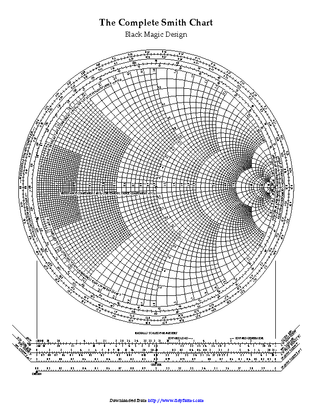
Load Reflection Coefficient and Normalized Load ImpedanceĮquation (2.4) expresses the load reflection coefficient in term of the normalized load impedance. Smith Chart is based on the plot of the load reflection coefficient utilizing this normalized load impedance, as explained next. Where the small letter L denotes the normalized load impedance, i.e., L = L / Z C. (1.1) and divide the numerator and denominator by the characteristic impedance of the line, Z C. Let’s return to the load reflection coefficient given by Eq. Shown in Figure 4 is also a unit circle, which sets the boundary for all the points representing a passive load reflection coefficient. The magnitude of 0 (center of the complex plane) corresponds to a matched load, the magnitude of 1 with the angle of 0 º represents an open circuit, while the magnitude of 1 with the angle of 180 º represents a short circuit. The angle is measured counterclockwise from the right-hand side of the horizontal Γ r axis.įor passive loads, the magnitude of the load reflection coefficient is always The magnitude of the load reflection coefficient is plotted as a directed line segment from the center of the plane.
Figure 4: Load reflection coefficient and the complex Γ plane

